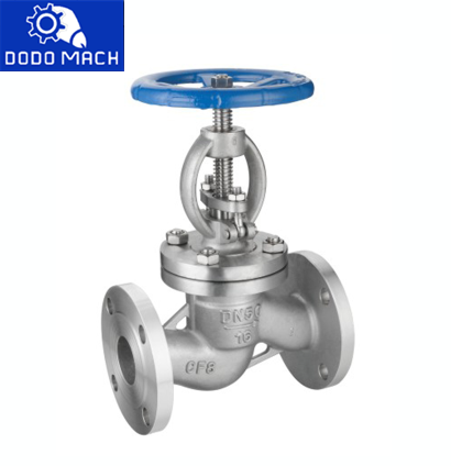
A globe valve is a key device used for opening and closing pipeline systems and regulating flow. Its core structure consists of a movable disc valve and a fixed ring valve seat, which are precisely matched to achieve flow regulation and precise control functions. The valve is named for its unique spherical body structure.
Globe valve parts and working principle
The globe valve adopts a double-cavity structure design to enable independent control of the fluid medium. Its operating mechanism is through the handwheel or actuator to drive the valve stem rotation, thus driving the valve spool (valve) to complete the lifting movement. The specific workflow of the valve can be broken down as follows:
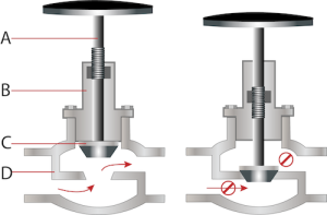
Movement of the disc: The key action of a globe valve is the relative movement of the valve flap (or valve plug, see Figure 1, labeled C) against the fixed valve seat. The valve flap is connected to the valve stem (Figure 1 labeled A) and external drive device connected to the drive mode, including manual (handwheel operation) or automatic (pneumatic, hydraulic, and electric actuators). When the actuator or handwheel rotates, the valve stem drives the valve flap to move linearly along the axis to realize the closure or separation from the valve seat.
Flow regulation: When the valve is open, the medium flows through the annular channel formed by the valve and the valve seat. With the valve closed, the valve flap gradually close to the valve seat, the flow cross-sectional area correspondingly reduces, to achieve the flow regulation function. When the valve flap is finally completely affixed to the valve seat, the media flow is completely blocked. This progressive cutoff gives the globe valve excellent regulating performance, making it the preferred device in the field of flow control. When the handwheel rotates, the valve stem drives the valve flap to make a linear movement along the axis, realizing the closure or separation from the valve seat.
Sealing Mechanism: The seat structure is usually precision fitted to the flap contour to optimize sealing performance. Some special designs use soft material flaps or surface plating techniques to further enhance the fit of the sealing contact surfaces.
Advantages of globe valves
Excellent flow regulation performance: globe valves with precise media control can realize the flow of fine-tuning operation; this feature plays a key role in systems requiring frequent adjustments.
Excellent sealing performance: the valve can achieve complete sealing in the closed state, which is decisive for system maintenance and emergency shut-off conditions.
Convenient maintenance: Adopting the structure design for easy maintenance and easy access to critical components effectively shortens the maintenance cycle and reduces operating costs.
Maintainability Advantage: Valve flaps and seats can be replaced or repaired to extend equipment life and maintain optimum operating efficiency.
Disadvantages of globe valves
Fluid Resistance Characteristics: Globe valves have a significant pressure drop, which is their inherent disadvantage. To alleviate this problem, Y-type or angle structure design can be used to reduce the turbulence effect and pressure loss. When determining the flow parameters of the valve, it is necessary to focus on evaluating the pressure loss factor.
High Torque Requirement: Globe valves require a large driving force to operate, especially under high-pressure conditions, and are usually equipped with automatic actuators for effective control.
Opening and closing speed limitation: the operating characteristics of multi-turn rotation make its response speed slower, not suitable for working condition scenarios that require fast switching.
High–pressure differential sensitivity: and is susceptible to cavitation and flashing under significant differential pressure conditions, which may result in damage to the internal components of the valve.
Economic considerations: Due to the relatively complex structure and high manufacturing process requirements, the cost of globe valves is generally higher than that of other conventional valve types.
Application of globe valves
Globe valves demonstrate excellent suitability in service conditions where precise flow control is required and where the pressure drop factor is acceptable. Typical application scenarios include:
Heat exchange system (cooling water circulation)
Power unit (fuel delivery system)
Water treatment unit (feed water and chemical dosing)
Thermal equipment (e.g., boiler systems and steam vents)
Rotating machinery (turbine lubrication circuit)
Fire protection facilities (sprinkler system, drainage, and regulating functions, but not suitable for high-pressure fire protection main control circuits)
Globe valve design variations
Flow path design
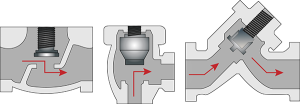
T or Z globe valve (Figure 2 left):
Structural features: the use of a Z-shaped flow channel design, the fluid needs to undergo two changes in direction.
Performance characteristics: excellent throttling performance, accurate flow control
Fluid characteristics: significant pressure drop, L/D factor of about 340
Typical application: working conditions requiring precision flow regulation.
Angle globe valve (in Figure 2):
Structural features: 90° right-angle valve body, single flow direction change
Performance Advantage: It reduces pressure drop by approximately 84% compared to Z-design (L/D factor 55)
Dual function: both pipeline steering and flow control
Applicable scenarios: Installation locations where a pipeline direction change is required
Y globe valve (Figure 2, right)
Innovative design: Oblique valve seat to form a gentle flow path
Technical advantage: maintain the throttling capacity while reducing pressure loss by 55% (L/D coefficient of 150)
Flow path optimization: significantly reduces the energy loss caused by sudden changes in flow direction
Engineering value: balances regulation accuracy and energy efficiency.
Plug design
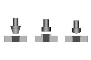
Plug disc: Adoption of a conical rigid structure, through face contact to achieve precise adjustment and reliable cut-off. The advantages of the structure are reflected in the excellent durability and sealing performance, especially suitable for high-precision flow control conditions.
Composition disc: The replaceable soft spools (typically made of rubber or PTFE) combine resilient sealing with resistance to particulate damage. This design provides excellent sealing reliability in contaminated media.
Ball disc: Featuring a spherical shutoff element with streamlined flow paths and fast shutoff capability. Their ease of maintenance and smooth operation make them ideal for moderate control requirements.